
Microcontroller
– Arithmetic and Logic Unit
– Control Unit
– Memory Input/Output
– First Microcontroller IC
Programming
Pulse Code Modulation
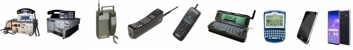
Digital Electronics for Cellular Telephony
The technology that was deployed in the 1980s was developed in the 1970s. Following Mores Law, Integrated Circuits contained more and more transistors. This lead to the development of better memory ICs with more content. Those where volatile memories, RAM, that lost their content when they were not powered. But also non versatile and „programmable“ memory became available so called EPROMS.
Beside memory ICs, more complex logic was developed wich finally lead to the availability of programmable controller ICs. In the 1960s controllers where still be created with a lot of separate logic devices. In the 1970s it was possible to integrate complete computing units on a single IC. Microcontrollers and microprocessors became available.
Microcontroller
Already in the early 1980s a mobile phone became too complex to be controlled with simple digital electronics. What was missing was programmability that was previously only known from computers.
A CPU, central processing unit, of a computer consists of several elements
- The Arithmetic and Logic Unit (ALU)
- The control unit (CU)
- Memory input and output
The Arithmetic and Logic Unit
In complex devices such as a mobile telephone, values must be queried and decisions must be made based on the corresponding value. For example these decisions can be logical decisions such as the logical AND as we already discussed. In an AND operation there are two input values that are compared and an output value as a result. The result is either TRUE or FALSE.
But you can also do other operations with two input values. For example, you can add two values or subtract them from each other as it would be required for a calculator. However, it is not practical to have a separate electronic unit for each of these operations. It is better to have a single unit whose operations can be set or „programmed“. Such a unit is called an arithmetic and logic unit (ALU). An ALU has two input values and an output value and a couple of „control signals“ that „program“ the required operation.
Control Unit
Who decides what operations are carried out in an ALU? This is the control unit. The control unit has an input field that contains the “command”. This is nothing more than a sequence of 4, 8 or 16 bits. The CU interprets this command and thereby switches the ALU to a specific operation.
All commands are stored in a memory. Every time a command is executed the next command is loaded. To do this, a counter is used, that points to the corresponding memory element, the „program counter“. This counter is incremented after each command.
But there are not only commands that set the ALU. There are also commands that move data back and forth. For example, from a memory into the input memories (registers) of the ALU or from the result register of the ALU into the memory.
Commands that refer to a result of the ALU are especially important. For example, there is an instruction that can set the program pointer to a special value if the result is TRUE. If the result is FALSE, it just increments the pointer. This makes it possible to perform conditional jumps to alternative program locations.
Memory Input and Output
As already described, you need a memory in which data and programs can be stored. A memory has special lines to transport the data. Dependent on the width of the data it consist of 4, 8 or 16 lines. (Today it is up to 64 lines). Those lines are called busses. There are two busses connected to a memory, a data bus, that carries the data, and an address buss that points to the location of the data in the memory. With 8 lines it is possible to address 256 locations. With 16 lines this is already 65,536 locations. 1024 (corresponding to 10 bit) is called 1 k memory. 65,536 is called 64 k memory.
There are memories with fixed content. These are typically the memories in which the program is stored. Such memories are called Read Only Memory (ROM). But there are also memories that can be read and written. This is called Random Access Memory (RAM).
Data is typically read or written to memory. However it is also possible to read and write to registers that are accessible to the outside world. This way it is possible to get „input“ and create „output“. Input is e.g. coming from a key board and output is send e.g. to a display controller.
First Microcontroller ICs
Processing units as described above, with an ALU, a control unit and a storage unit, have been available in the first large computers since the 1950s. However, these were extremely large cabinets and completely unsuitable for electronic devices such as a mobile phone.
The breakthrough came from the electronics industry that was looking for simple and practical solutions for calculators. In the beginning this was just addition, subtraction, multiplication and division. An addition or subtraction is still relatively easy to do with logic, but as we all know from school, multiplication and division requires a sequence of additions and subtractions. Therfore, for multiplication and divisions a programmable solution was needed.
As already mentioned, the Intel company was founded in 1968. The founders were from the famous treacherous Eight of Fairchild. Intel was initially specialized in building ICs for memory. But they were also open to commissioned work. One such order came from a Japanese company that wanted to build a small electronic calculator. For this they needed an effective and small processor. This simple processor was created at Intel in 1971. It was called Intel 4004. Intel later bought the license for the 4004 from the Japanese company and sold the world’s first simple microcontroller or microprocessor. It was only a 4 bit system, i.e. the data was only 4 bits wide. And it was very slow. The sequence of commands (clock frequency) was only 500 kHz. (Today it is several GHz.) The design contained only 2300 transistors.

The Intel 4004 was not the only processor. Soon there were also microprocessors from Texas Instruments and Motorola. There was also soon a change from 4 bit processors to 8 bit processors.

Programming
In the late 1970s, more and more microprocessors were installed in mobile phones. This dramatically reduced the number of components required and thus size and power consumption. It also brought a new breed of engineer into the mix. Until now there was the common electronics engineer, later also called the digital electronics engineer, and the radio-frequency (RF) engineer, who was responsible for sending and receiving. Now the „programmer“ came in and programmed the built-in microcontrollers.
There was a difference between “normal” computer programmers and those who programmed a microcontroller. The large computers had large magnetic memories in which the programs were stored. When a program was executed, the program was loaded into local storage. Microprocessors didn’t have this luxury. The programs actually came (as with pocket calculators) from a ROM, i.e. a read-only memory in which the program is „burned in“. This was designed once and then manufactured as a special IC. By nature it could not be changed. However, with increasingly complex tasks, it became practically impossible to create a bug-free program and make a ROM out of it without having bugs (SW errors). It was not possible to program a new ROM quickly because producing a ROM takes several weeks.
Help came from another Intel invention, the EPROM. EPROM stands for Erasable Programmable Read Only Memory. Programs (and/or data) could be permanently stored in these blocks (non volatile Memory). The programs were downloaded from a „Laboratory computer“ and “burned in” using special loading devices. Now it was possible to “try out” the program with a microcontroller. Of course, errors occurred that needed to be corrected. The EPROMs in question had a “window” to the chip. UV rays could be let in, directly to the chip through this window, which caused the previously programmed data to be deleted. After that the EPROM could be reprogrammed. This is how the engineers of the 1970s and 1980s programmed their systems.

Pulse Code Modulation
Until World War II, there were only two methods for storing analog signals, especially audio signals. Either mechanical storage, for example on records, or magnetic storage, for example on tapes.
Even before the war, theories were developed on how to “scan” signals. The idea is that you measure the voltage of a signal at a certain point in time and store the value of that measurement. If the measurement is carried out at periodic time intervals, a sequence of numbers is obtained which presents the signal. Conversely, if it is possible to generate voltages at periodic intervals that correspond to the stored numbers, it should be possible to reconstruct the same or at least a similar signal.
Although it was not possible to actually sample signals before WWII, there were theories as to the frequency at which signals had to be sampled. It was primarily an engineer named Harry Nyquist who discovered that the frequency at which a signal is sampled must be twice as high as the highest frequency of the sampled signal. If this is the case, it is possible to reproduce the signal from the sampled sequence of numbers.

Under certain conditions, analog signals can be converted into number sequences and vice versa. This allows signals to be processed digitally.
Speech (on telephone lines) has a bandwidth of less than 4 kHz. Therefore, speech signals can be sampled at a frequency of 8 kHz. But how exactly do you have to sample each individual value? Economically, a signal cannot be measured with high precision. If the measured value, which corresponds to a number at the end, deviates from the actual value, it creates a small error and the succession of random „errors“ appears as noise. This is called the quantization noise. It was found that an 8 bit was sufficient to create a good relationship of the signal in relation to the quantization noise since it had approximately the same level as the noise that was always present on telephone lines.
In 1972, a standard for sampling telephone signals was created, known as pulse code modulation (PCM). Linear sampling with 8 bit precision and a sampling rate of 8 kHz. This creates a data rate of 64 kbit/s.

Devices that sample signals and generate number sequences are called analog digital converters (ADC). Conversely, a digital analog converter (DAC) generates the analog signals again from a sequence of numbers. ADC and DAC were already available as ICs in the early 1980s. They were primarily built and sold by a manufacturer called Analog Devices.