
New Frequency Bands for the C-Netz
Organisation Channel
– Frequency Shift Keying
– Frame Structure
– Synchronization
– Error Correction
Selection of the Base Station
Sign In
Inband Coding
Digital Signal Processing
Subscriber Identification
Deployment and Devices
Description of the C-Netz
When the good old „B-Netz“ was rolled out in the 1970s, people were already working on the next mobile radio system, the „C-Netz“. This was intended to be a truly modern cellular network with the incredible number of up to 800,000 subscriber. In 1976 it was advertised by the German PTT „Deutsche Post“. This time it was not TeKaDe that won the tender, but Siemens. Siemens engineers designed a system that promised to be the most optimal use of the newly available frequencies.
New Frequency Bands for the C-Netz
New frequencies for the C-Netz were in the 70 cm band at 450 MHz. There was a 4.44 MHz wide lower band and upper band with a spacing of 10 MHz. 222 channels with a width of 20 kHz were available.

The transmission power of the mobile stations was variable, which was great advantage for efficient operation. When the mobile station was close to the base station, it was possible to operate with reduced power to save energy and reduce interference. The maximum power was 15 W, the minimum power was 5 mW.
Organisation Channel
For the first time, a purely digital channel for communication between the terminal device and the base station was introduced in the C-Netz. Such a channel had a so-called frame structure. This meant, it was divided into so-called time slots. The corresponding information is displayed digitally in these time slots, typically encoded with two different frequencies. To detect the beginning of such a digital sequence a special digital structure for synchronization was introduced.
Frequency Shift Keying
In the C-Netz, the digital control channel is called the organizational channel. The data it contains is encoded with the change between two frequencies (frequency shift keying FSK). This channel is the same for everyone, including all base stations. This requires all base stations to be synchronized to less than one ms accuracy. The organization channel, like all other channels, had a sub-channel (from mobile station to base station) and an upper channel (base station to mobile station).
Information are stored digitally by having a Null related to one frequency and a One related to a different frequency.
Frame Structure
The organisation channel has a frame length of 2.4 s and is segmented into 32 time slots.

Each time slot has a length of 75 ms and consists of two halves, a call part and a response part. The call part is for the mobile station to report to the base station. The response part is mainly used for communication from base station to the mobile station.
Each base station is assigned to a time slot on which it can send and receive. The time slot distribution, like the distribution of the channels for the radio cells, must therefore be planned precisely.
Synchronization
Communication takes place via the call or response block. Both have the same structure. First of all there are 7 bit pause at the borders. Then it starts with a synchronization sequence of 33 bits. This synchronization sequence is a special sequences of 1 and -1. The synchronization happens as follows. The incoming 33 bits are always compared with the stored synchronization sequence. This is accomplished by multiplication, which can be done very easily using Logic. (1×1 =1, 1×0=0, 0x1=0 and 0x0=1. Multiplication therefore corresponds to a logical AND operation). Now the result is added. Such an operation is called autocorrelation.
The Barker codes that are used for synchronization have the property that the autocorrelation always results in a very small value, unless the sequences are exactly on top of each other. Then sum is maximum, in our case 33. Using this autocorrelation, the start of the information bits that follow the synchronization can be detected precisely.

Synchronization through autocorrelation is a recurring method for synchronizing transmitters and receivers in digital transmissions.
Error Correction
70 information bits are transmitted along with 80 redundancy bits. These are not separated as in the figure, but are interleaved. So-called BCH codes are used for to generate the redundancy. They allow up to 20 transmission errors to be corrected. However, this task also requires a quite sophisticated algorithm. The procedure of adding/creating redundancy bits and later using them for error correction is called channel encoding and channel decoding,
Selection of the base station
When a mobile station is turned on it begins to synchronize to the organization channel. After synchronization it can measure and evaluate the reception level of the various time slots. This gives already a strong indication about the nearest base station.
The mobile station saves the results. As discussed above, a mobile station can use synchronization to determine very precisely when a block of information begins. The bits are transmitted at the speed of light. Thus, a block of information from a nearby base station arrives earlier at the mobile station than that from a more distant base station. The mobile station now measures the time difference between the signals from the different base stations candidates. This allows an additionally estimate which base station is nearer. The accuracy of the distance measurement was about 250 m.
Sign in
Finally, the mobile station sends a message to the base station in which it communicates its identity. The base station acknowledges the login and sends a message to the mobile switching center (MSC). An entry in the so called home location file is made by the MSC, in order to note that the mobile station is active and where it is located.
The mobile station continues to carry out measurements of the base stations. Typically up to seven base stations are checked. If the mobile station moves, it may happen, that the mobile need to abandon a call. In this case the cell is changed in collaboration with the base station and the new location of the home location register is entered.
The conversation is also established via the organizational channel. The phone number is passed through and a connection is created to the landline telephone network. A free channel is assigned to the mobile station is then assigned on which the conversation takes place using regular frequency modulation.
Inband Coding
As discussed above, the mobile station must also communicate with the base station during a voice connection. For this purpose, in addition to the “user data” (the voice), “control data” must also be transmitted. To achieve this, the C-Netz is also deciding the voice channel in time slots of 12.5 ms length. This creates „Voice slot“. These are now compressed to 11/12 of their original length, they are „compressed“. This creates small gaps between the voice slots that are large enough to accommodate 4 bits of data. So 320 bits information can be transmitted per second. Enough for the necessary data exchange between base station and mobile station.

When it comes to voice transmission, the following steps occur.
- Division into time slots, storage of a voice blocks of 12.5 ms length
- Compression of the stored voice block
- Insertion of a signal which corresponds to the FSK coding of 4 bit data
- Transmission of the generated signal via the radio channel
For the reception the following steps applies:
- Division into time slots and storage of 12.5 ms length
- Extraction of the data block and decoding of the 4 bits
- Decompression of the voice part to a length of 12.5 ms
- Delivery of the voice signal and further processing of the digital data
But how is it possible to store and compress an analog signal?
Digital Signal Processing
With the help of analog to digital converters (ADC) and digital to analog converters (DAC), it is possible to compress and decompress speech signals. First, a digital signal is generated by „sampling“ the speech signal (see PCM). Compression can now be achieved by running the DAC faster than the ADC. This is like recording a signal on a tape and playing it afterwards with a faster speed.
Let’s assume we sample at 8 kHz, then we get 100 speech values in 12.5 ms. Now we add 10 values that correspond to the 4 bits of information and get 110 values. We now output this with a sampling rate of 8 kHz * 110/100 = 8.8 KHz. Since 110 values now correspond to a time of 12.5 ms, we get the desired transmission signal. Conversely, we have to sample the received signal at 8.8 kHz and can extract the information bits and the speech signals from it. This process is already half digital because it uses very simple digital signal processing techniques but the speech signal is still transmitted in analogue form.
Subscriber Identification
Until now, the identification of mobile phone was permanently linked to the device. It was relatively complicated to transfer a telephone number from one device to another device. The C-Netz was the first system to separate the identity of the subscriber from the actual telephone. To do this, an „Intensification Card“ like a debit card or a credit card was used to hold the subscriber identification. This was initially done via a magnetic strip, later via an IC, located in the card. This innovative type of identification was adopted for the successor system GSM.
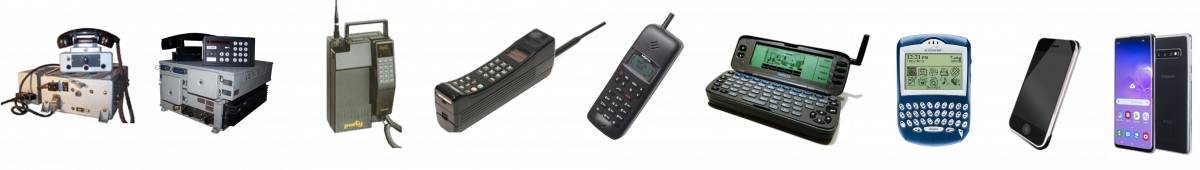
Deployment and Devices
The C-Netz was introduced in Germany in 1985. Beside Germany it was only used in Portugal and South Africa. The market was therefore national and dominated by the Deutsche Telekom. Focus was on car phones. Manufacturers were Siemens, Philips (formerly TeKaDe), SEL, Bosch, Storno (from Denmark). A key feature of these new telephones was that the control panel and handset were integrated. Handsets with integrated display and keyboard were created. These handsets could be installed on the driver’s side while the transmitter was plugged into an adapter in the trunk of the car. It was also possible to plug the handset directly into the radio part. This had a dry battery to make it independent from the car. In this sense it was no longer a car phone but a portable mobile phone.

The displays where advanced in a sense that they could not just display numbers but also letters. This meant that commands could be displayed or names together with phone numbers could be stored. Initially the displays were LED based but were later replaced by LCD displays to save energy.
In the 1990s, technology was already so advanced that it was possible to build small hand-held devices. One of the first was the Portel C3 from SEL, which was used by Angela Merkel.

The little „portel“ was already a sensation. A year later, Siemens came out with an even smaller device, the Siemens C4.
The peak of the C-Netz had already been reached in 1990. The industry was already working on the new digital successor. However, the reunification of Germany gave the C-Netz another boost. The GDR’s landline network was very poorly developed. It couldn’t be improved quickly. The solution was the C-Netz, which could be installed quickly. Many companies and private individuals bought a cell phone instead of waiting for a landline phone connection.
The C-Netz was finally shut down in the year 2000.